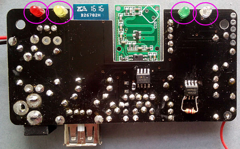
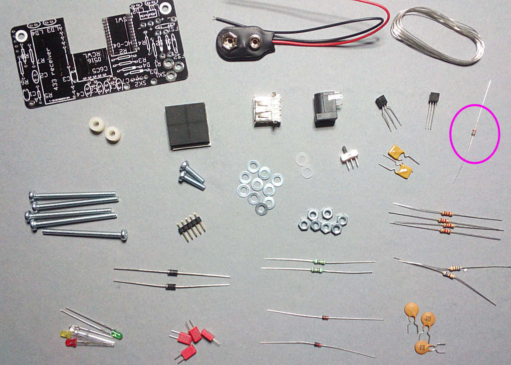
Now a few parts to fit on the other side. The LEDs don't have to be in this order but it will make the instructions easier to follow . The SHORT leg faces RIGHT for all four:
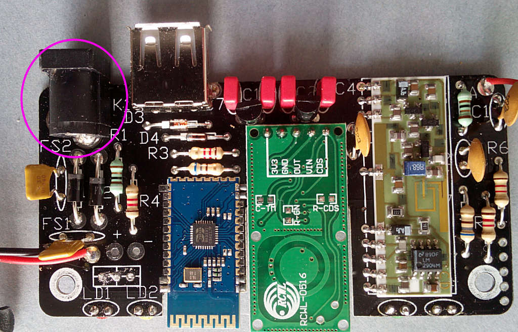
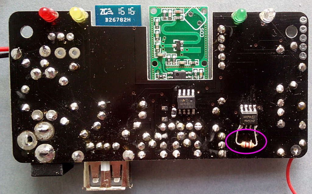
Time for the first power test. Connect the 15V power supply to SK1 and switch on. LED1 (red) should light - if not switch off and check your soldering.
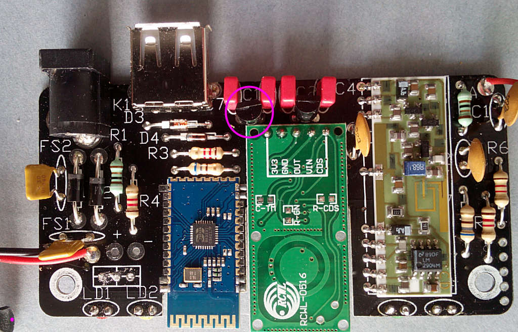
If LED1 is lit, check the voltage across C6 - this should be 3.3V, then across C4 which should be 5V. If they're wrong or missing check around IC1,2 and D1,2,3.
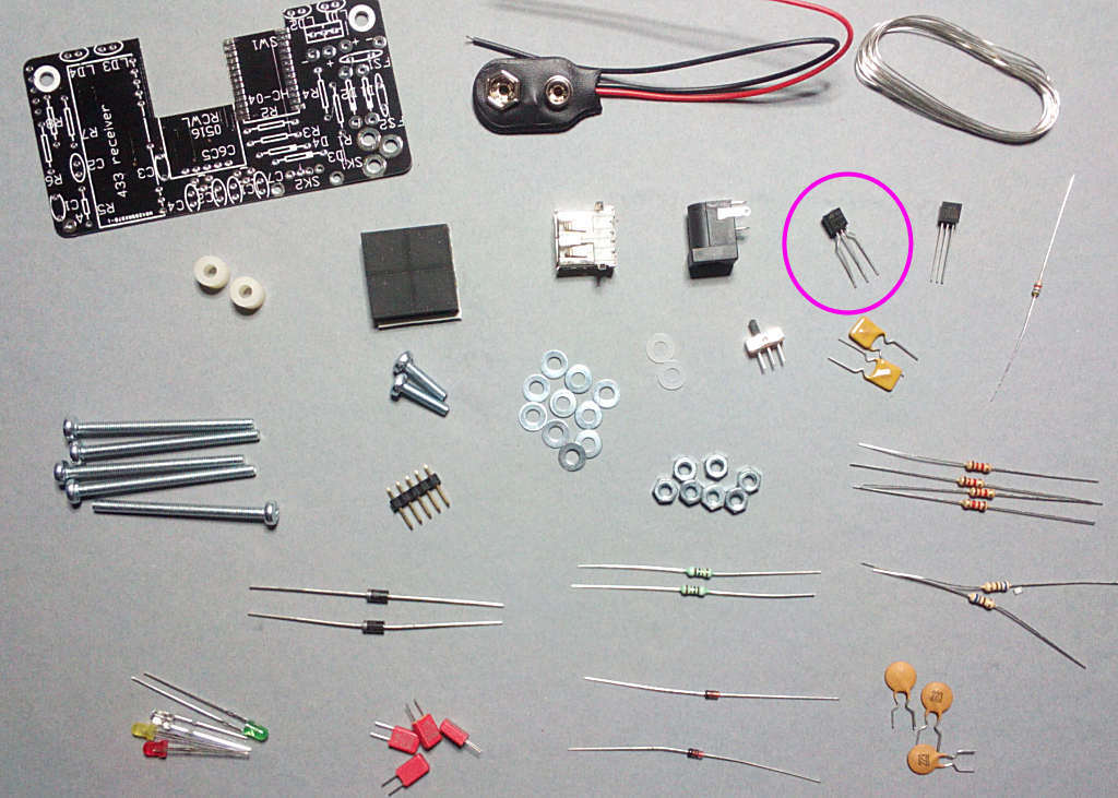
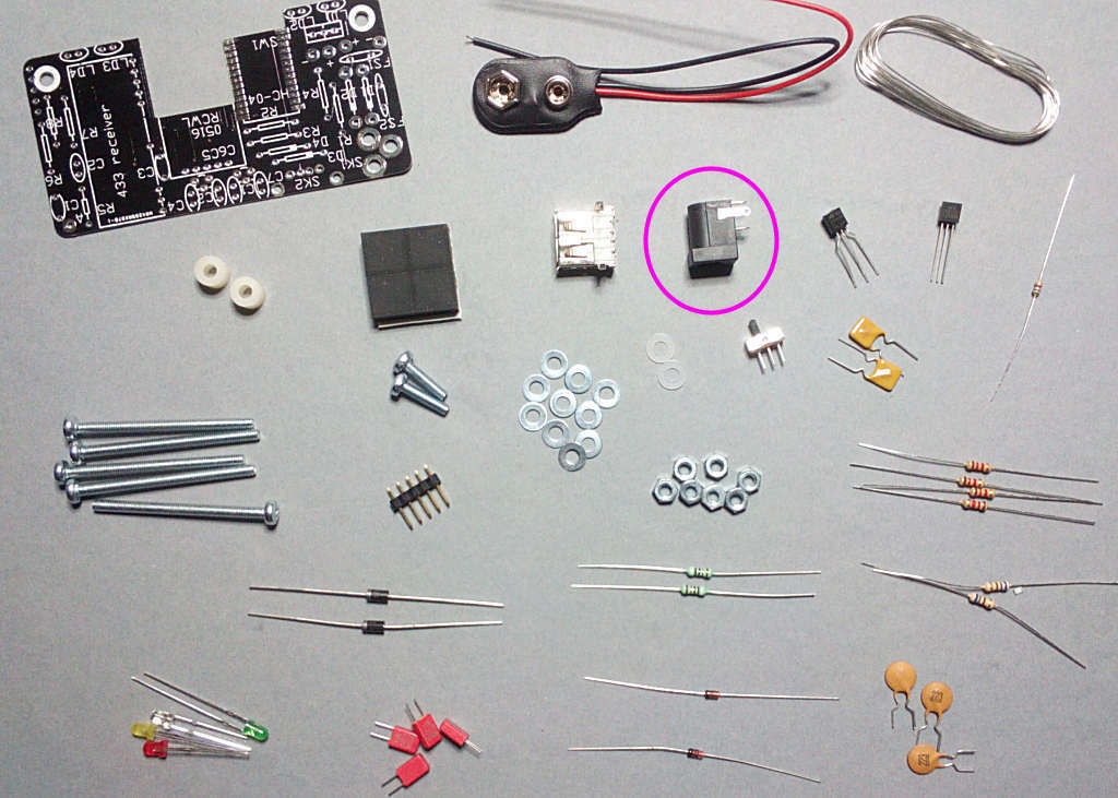
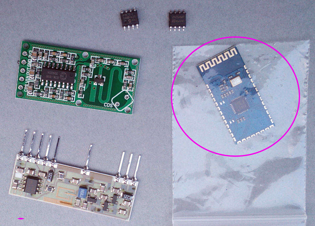
If the voltages are correct we can fit the more expensive components next.
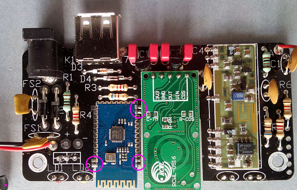
Finally the modules. Start with the Bluetooth module as it's the most difficult to solder into place. Note only the pads indicated need to be soldered: