Unpack and sort out the components into seperate piles. You should have:
2x 22k 1/4W Resistors[/*]
2x 1k2 1/4W Resistors[/*]
1x 4A quickblow Fuse[/*]
16x Ferrite filters (chokes)[/*]
65x 100uH Inductors[/*]
65x 4n7 capacitors (Green)[/*]
66x 10n Ceramic capacitors (Brown)[/*]
52x 33u 16v Electrolytic capacitors[/*]
14x 14V Zener Diodes[/*]
2x 5v1 Zener Diodes[/*]
1x Power socket[/*]
60x 2.5mm PCB interconnect pins[/*]
15-20g Lead free 'solder'[/*]
16x Coil driver PCBs[/*]
2x 'Spine' PCBs[/*]
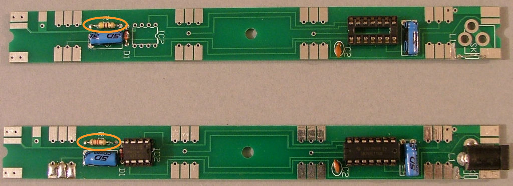
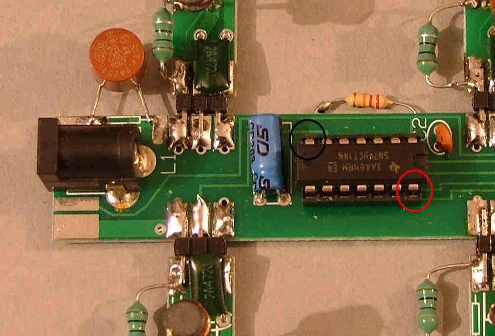
We'll start by assembling the 'spine' PCBs as these provide the power and drive signals for the coil drivers.
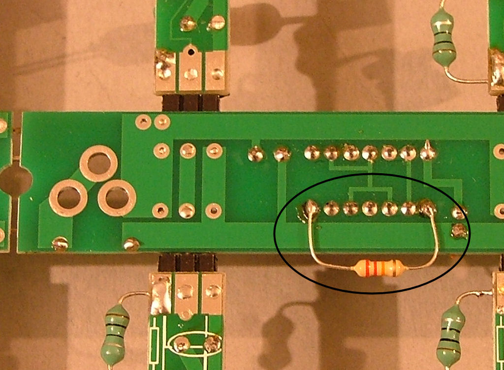
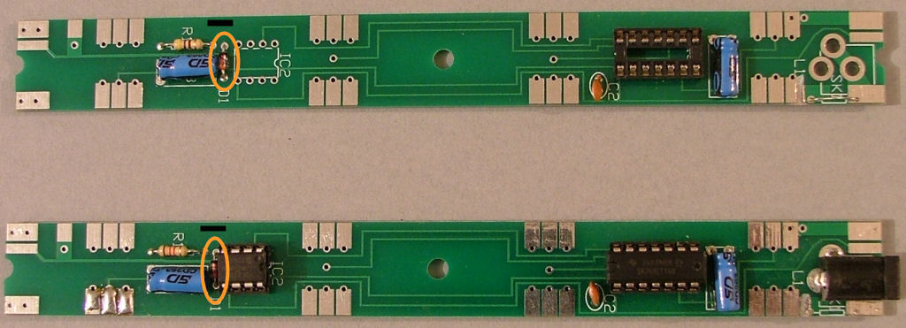
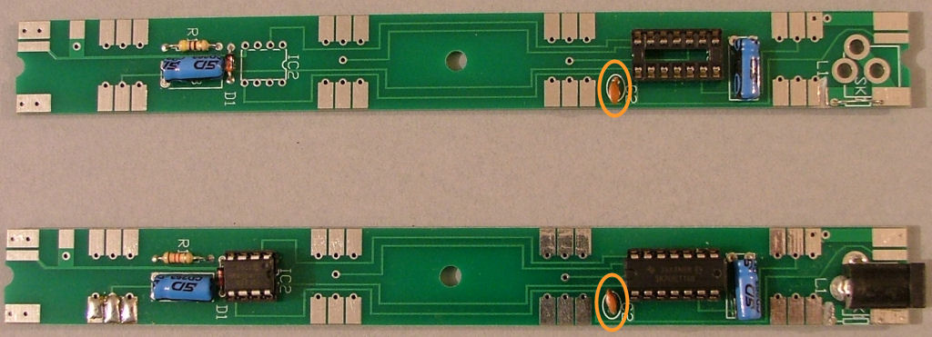
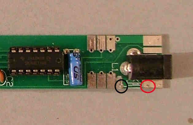
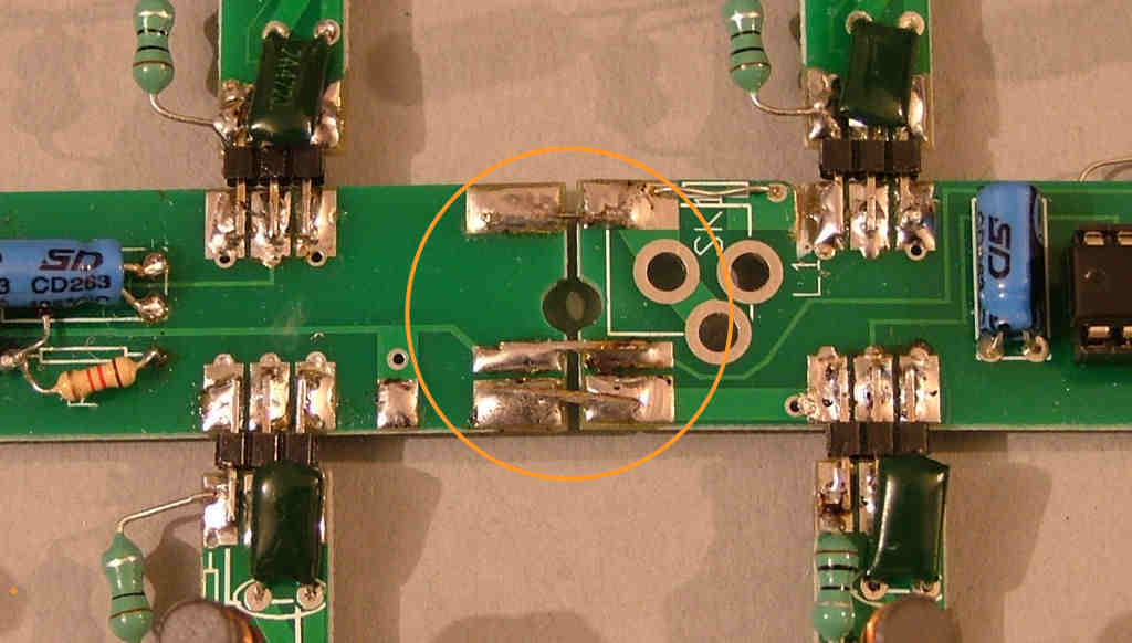
Before starting on the assembly, there's a small mistake in the PCB layout. The track next to F1 needs to be cut as it was moved by accident in the final layout and shorts the 12V rail to ground.
Cut it as shown here on both boards:

.